FIXING VGA/Z80 badly inserted card !
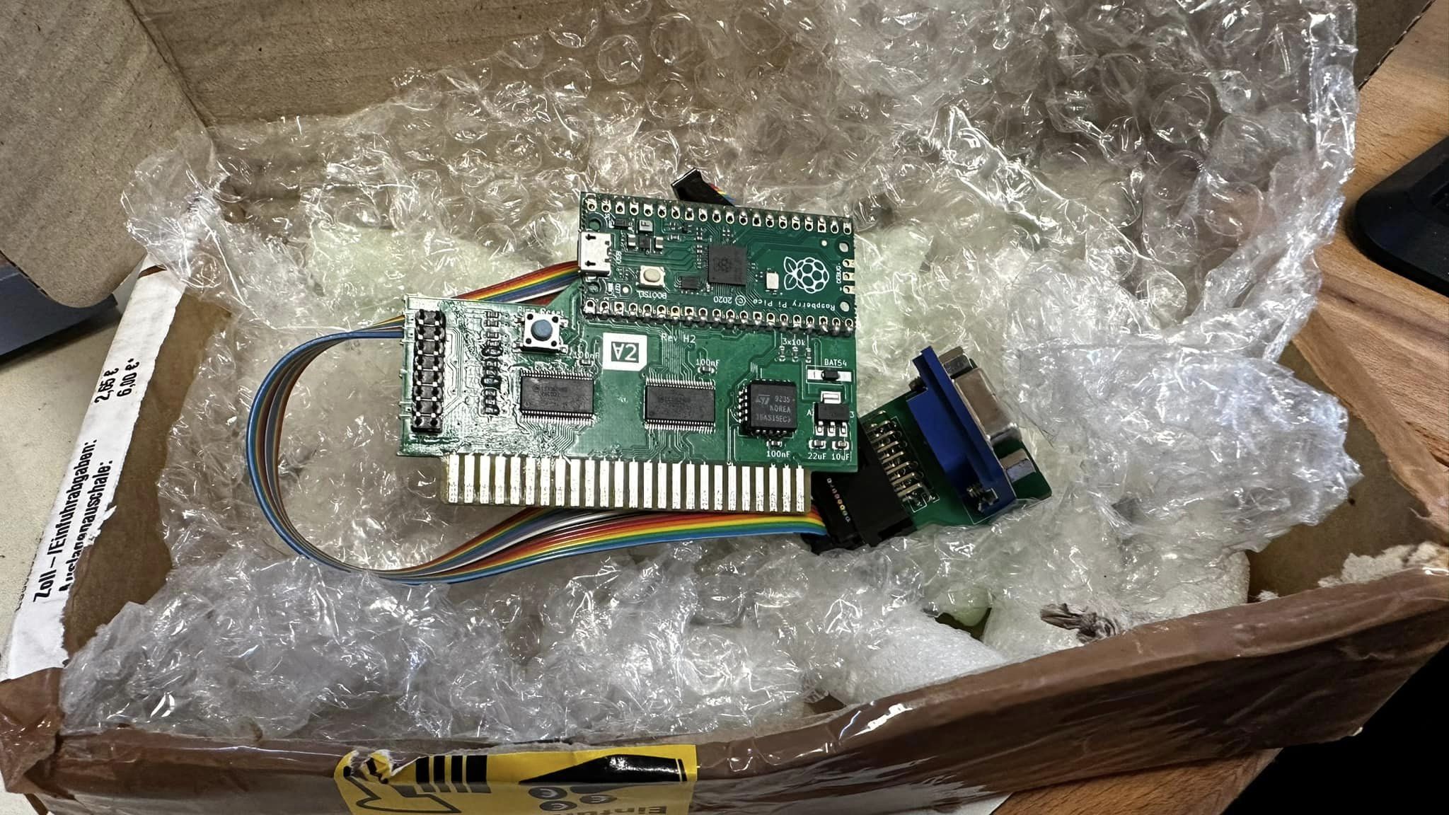
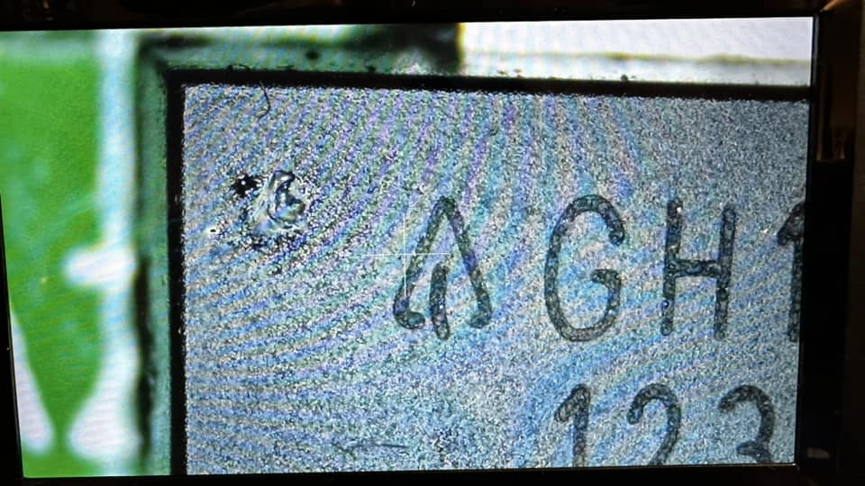
Received the broken V2Analog board from Bollington today which got inserted the wrong way into the slot.
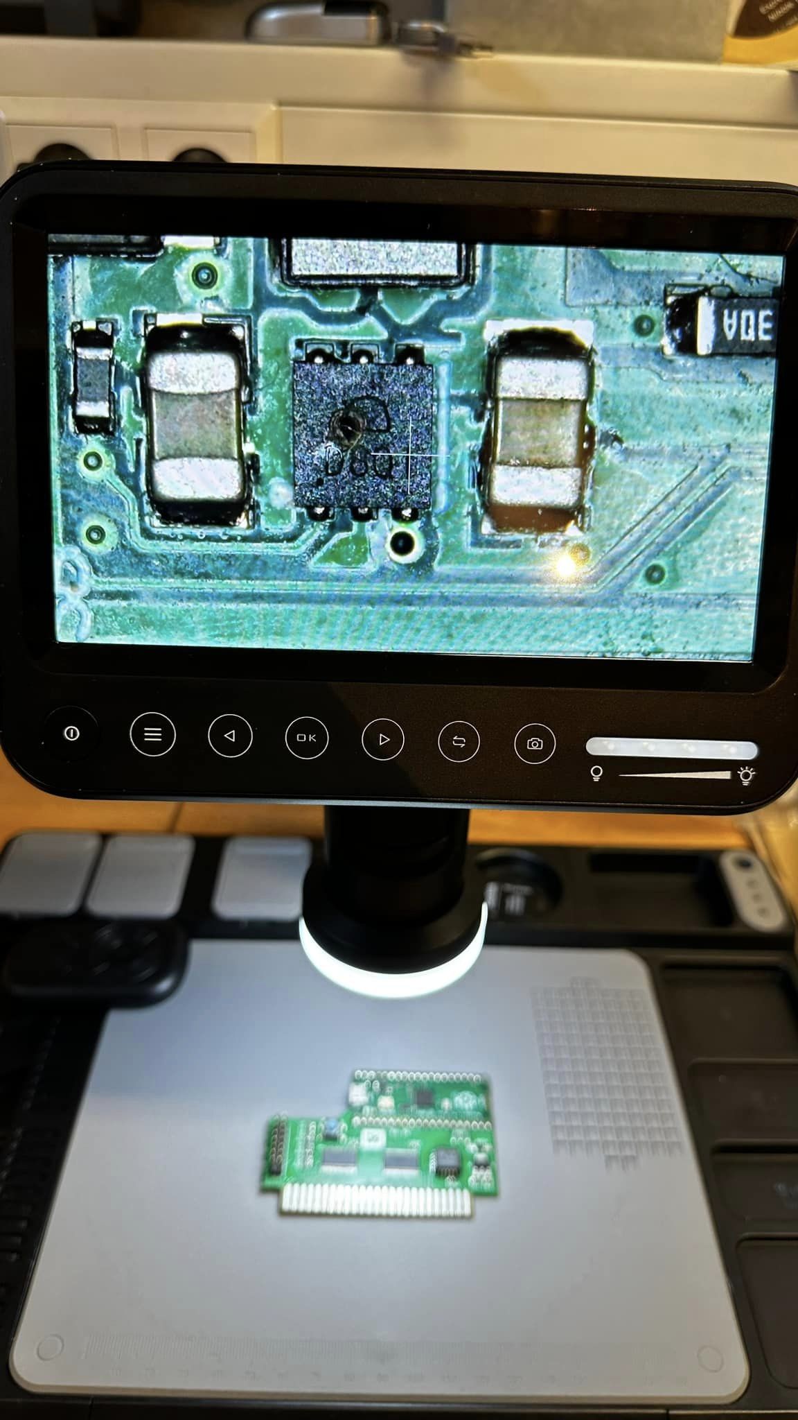
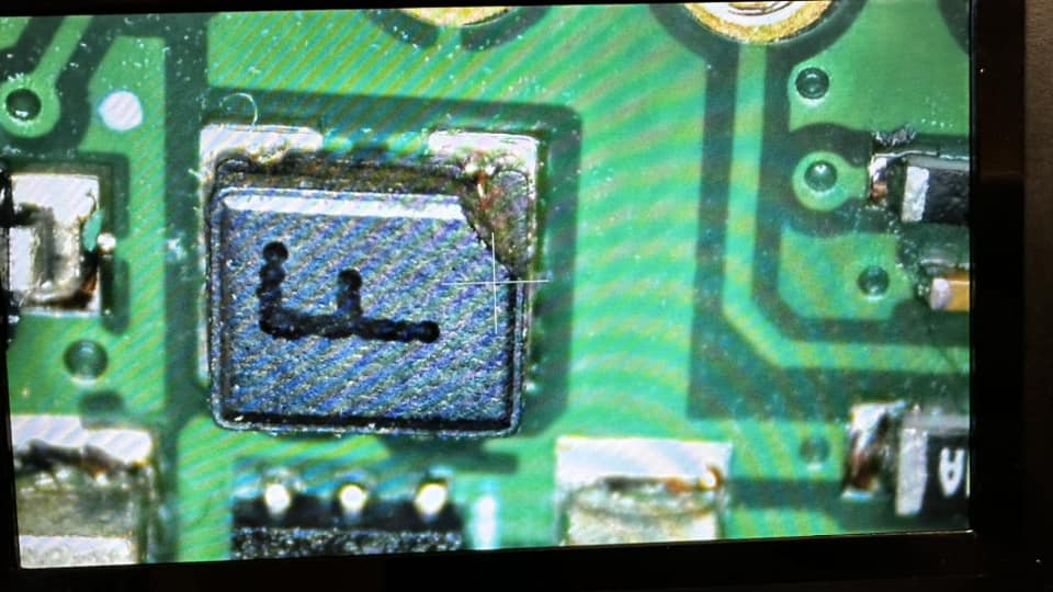
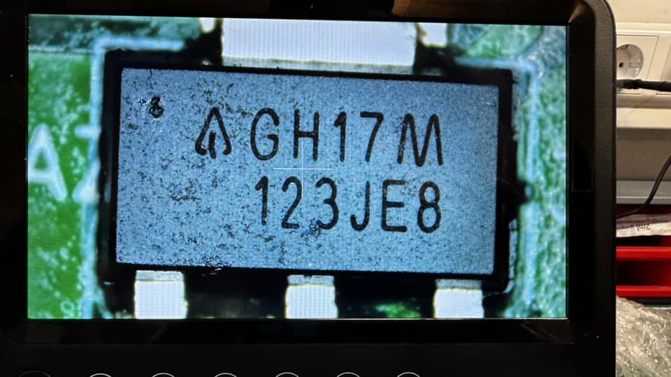
I could detect some damage on some of the chips which I want to replace then hopefully I can fix this
but it will be an interesting experience if it is possible to repair it and maybe be a guide for future
repair attempts. So let’s get to work on it…
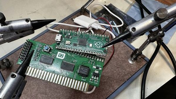
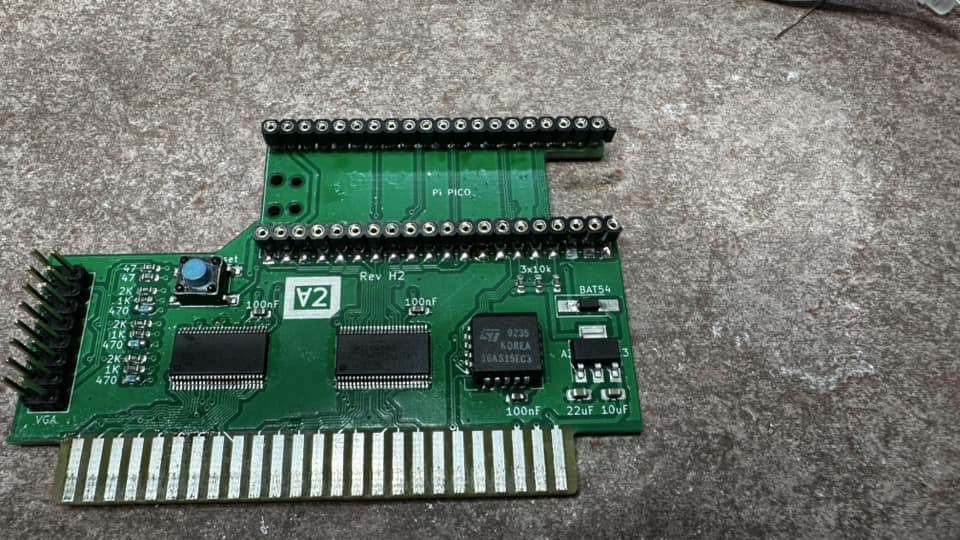
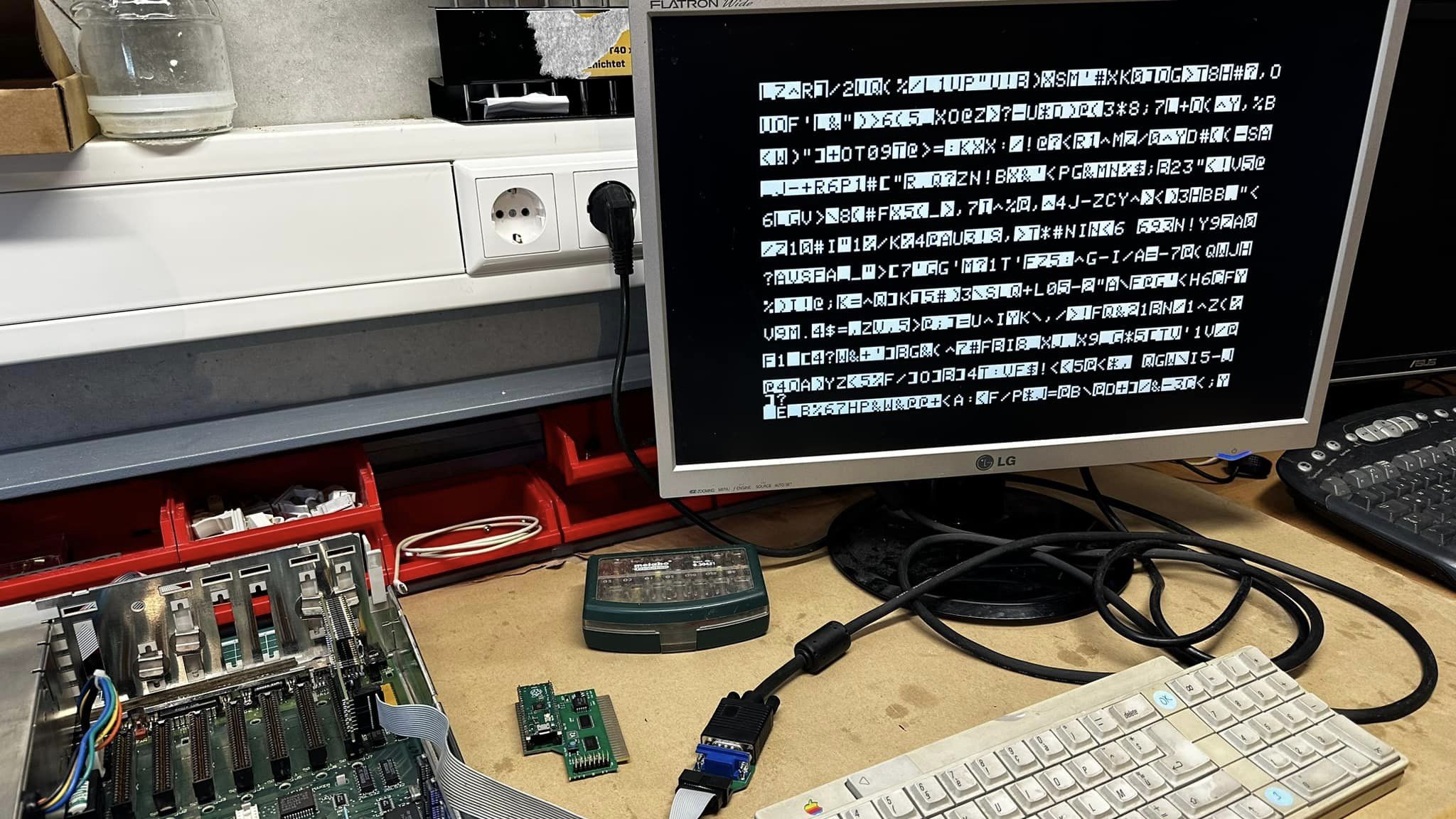
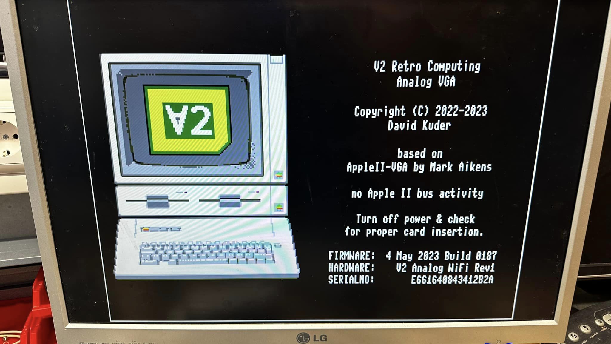
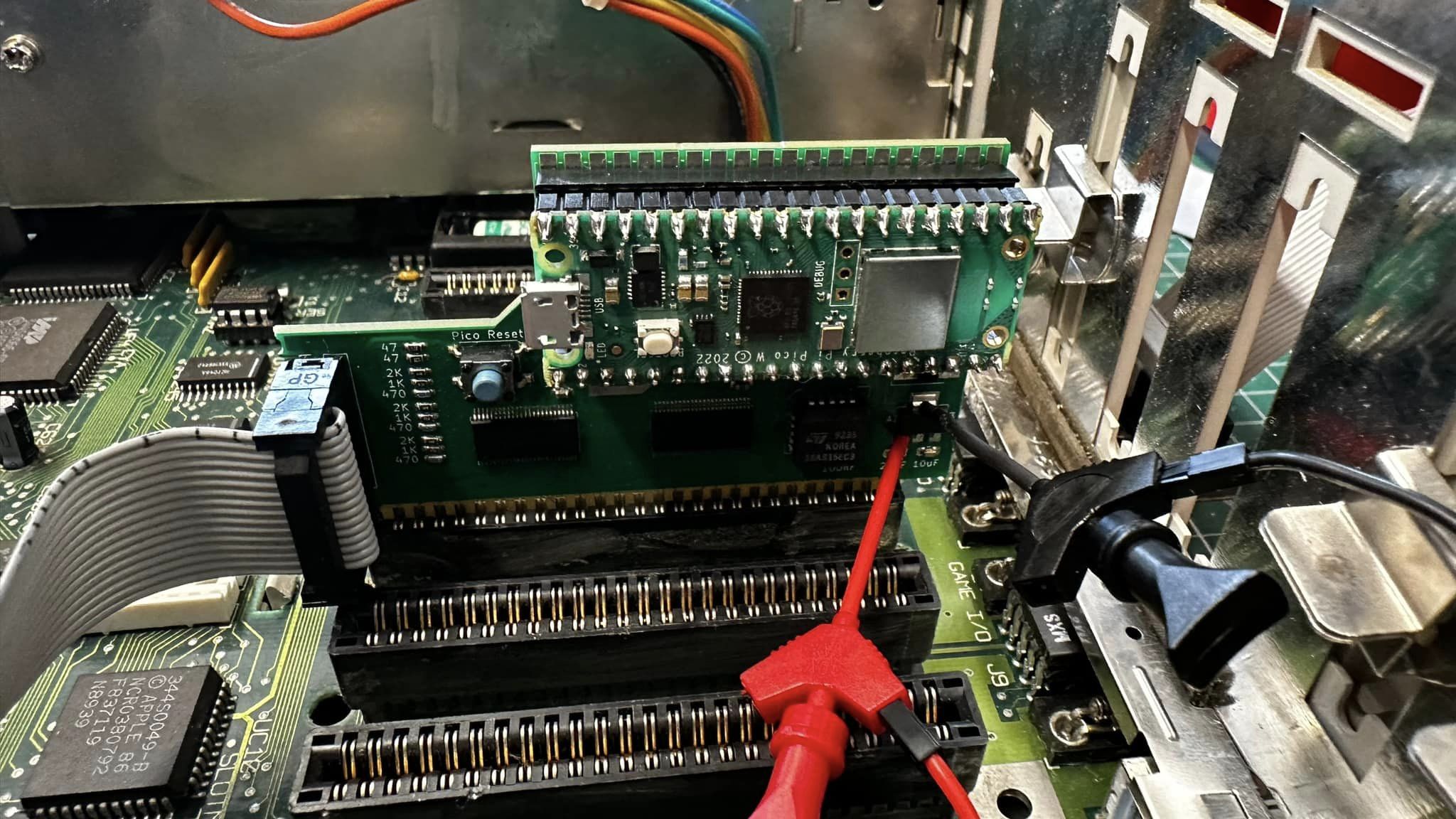
Successfully fixed the V2ANALOG clone.
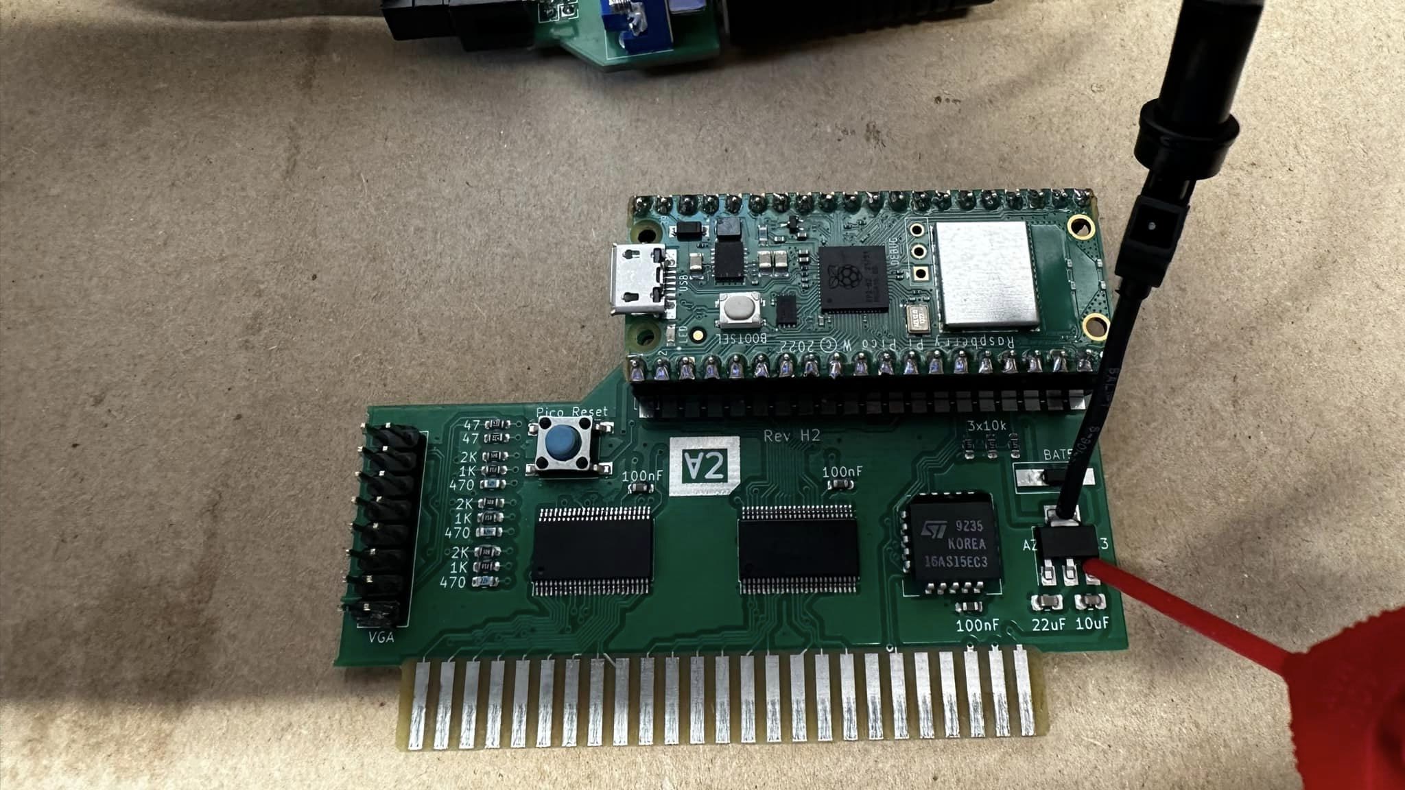
Inserting the card the wrong way results in a broken Pi and two damaged bus transceivers.
One disadvantage of the card is the direct soldering of the Pi on the board when it gets damaged it is
hard to remove it successfully. This took some time. The repair process was a step by step procedure
and in the end I had to replace both bus transceivers. But now the card is working again and will get
some extra parts that it cannot be inserted the wrong way again.
To Check : if it's not shorted -- ie GND pin to any of the voltages on the slot connector,
before you plug it in of course. There shouldn't be any short there -- if there isn't, you
are probably safe to put it in the IIe !
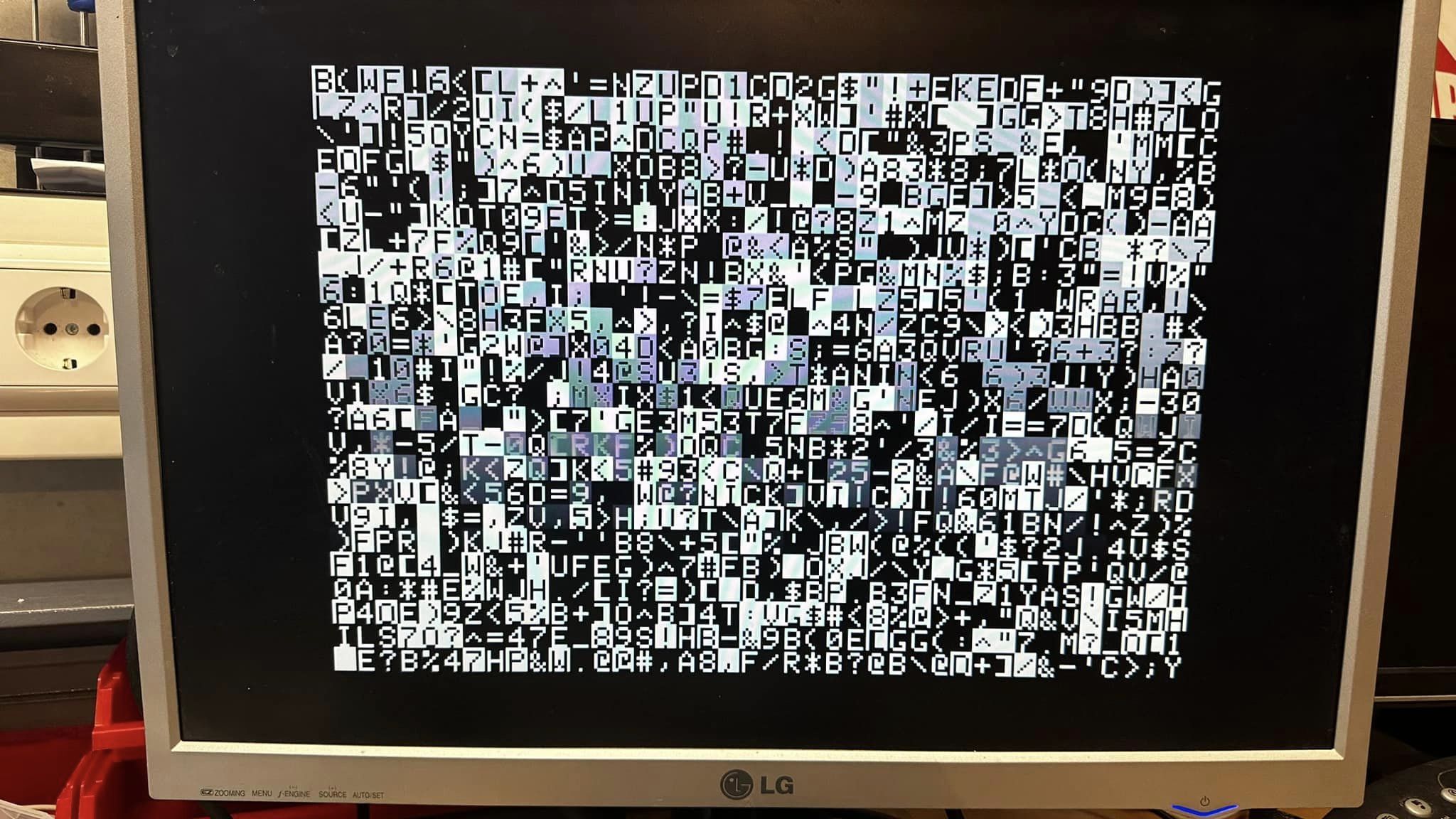
Most important is to avoid shorts between voltages and ground. I also had shorts to dress
and data lines when building the thing and that stopped the Apple from booting but did not
do any damage. I also had problems with heat gun soldering of the small components which is
really error intense so you might take your time. I built three clone cards altogether which
I got from a German reseller who did the clone design. His rationale was to reduce the number
of components by using two large bus transceivers which are easier to acquire compared to the
ones on the original V2Analog at the moment. Furthermore is he using only a double layer board
which is far cheaper compared to the four layer boards of the original card.